Wireless Arduino compatible PIR with LoRa or RFM 69 radio on board.


The easyPIRmultisensorsBox is a low cost wireless Arduino IDE compatible (the Atmel ATMega328P 8MHz) microcontroller with RFM 69 CW or RFM 69 HCW or RFM 95 LoRa radios on board and few other nice additions.
Best sutable for Home Automation, IOT. You may think of it as Arduino Pro Mini plus all the items in the picture below:

Specification:
- MCU Atmel ATMega328P 8MHz) microcontroller
- Radio- HopeRF RFM 69 CW or RFM 69 HCW or RFM 95 LoRa (915, 868 0r 433 MHz) radio on board
- Enclosure dimensions 95mm40mm20mm
- Powered by two AA batteries
- Booster converter alows to work from batteries drained as low as 0.7V combined
- Wide operating temperature range. Tested -20 +40 Celsius
- PIR sensor Am312
- Temperature and humidity sensor SHTC3
- High Accuracy Temperature Sensor ±0.4 °C (max), –10 to 85 °C
- Precision Relative Humidity Sensor ± 3% RH (max), 0–80% RH
- Light sensor BH1750, spectral responsibility is approximately human eye response.
- Authentication security - Atmel ATSHA204A Crypto Authentication Chip
- Dualoptiboot bootloader. Implements over the air (OTA) firmware update ability
- FTDI header for programming
- Reverse polarity protection.
- Arduino pins A0 A1 have pads on PCB for any special needs.
- PIR triggers interrupt PCINT23 D7
- Magnet sensor triggers hardware interrupt 1
Pin out:
| Arduino Pins | Description |
|---|---|
| A0, A1 | Available ARDUINO analog GPIO / DIGITAL GPIO as PCB pads close to radio module |
| A4 | Connected to sensors i2c |
| A5 | Connected to sensors i2c |
| A6 | Battery sensing voltage divider 1M/470k |
| A3 | Connected to ATSHA204A |
| D3 | Connected to Magnet sensor |
| D4 | Connected to RFM 69/95 DIO1 |
| D5 | Connected to GREEN_LED_PIN |
| D6 | Connected to RED_LED_PIN |
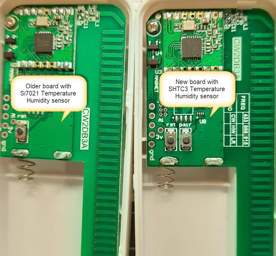
| D7 | Connected to PIR sensor PCINT23 (Older version of the board had PIR was connected to D3 INT1) |
| D8 | Connected to CS FLASH chip (OTA) M25P40 |
| D2 | Connected to RFM 69/95 DIO0 |
| D9 | Connected to RFM 69/95 Reset pin |
| D10 | Connected to RFM 69/95 CS/NSS |
| D11 | Connected to MOSI |
| D12 | Connected to MISO |
| D13 | Connected to SCK |

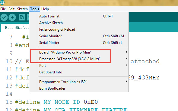
Arduino IDE Settings

programming FTDI adapter connection

Old and new versions

How to use it as home automation (IOT) node controller
easyPirPCINTdoorSensor.ino is the Arduino example sketch using MySensors API.
Connect the Node to FTDI USB adaptor, Select Pro Mini 8MHz board in Arduino IDE and upload the example sketch sketch. The skecth will create node fith fixed address in Mysensors network.
The Sketch will create a number of sensors for a controller which you can use or ignore (comment it out in the code). PIR_sensor - actual PIR sensor which toggles 0 and 1 when something moving around VIS_sensor - The code reports new LUX readings each time the PIR sensor wakes up the unit. DummyDimmerLUXvalue_sensor - well, this is a workaround for the PIR threshold. By default when a fresh unit uploaded with the new code, PIR sensor changes will always be reported. If you like to make it less sensitive add DummyDimmerLUXvalue_sensor as dimmer in the controller and set maximum LUX value when PIR reports movement. I could not find any easier way sending values back to the sensor from conroller so far.
HUM_sensor - humidity sensor. The code reports a new value if any changes in humidity readings happened after the PIR sensor wakes up the unit. TEMP_sensor - The code reports a new temperature if any changes happened after the PIR sensor wakes up the unit.
MAG_sensor - magnet sensor, since the board has the magnetic sensor soldered the sketch shares the same code as for door sensor. Same reporting logic for the temperature and Humidity applied for the magnet sensor. Comment it out if you do not need it.
Done
The board designed by Koresh